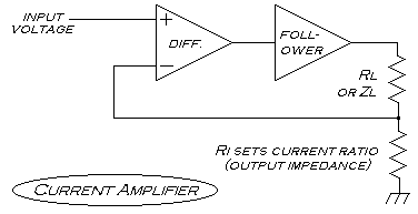
Hi, Here's a current amplifier, just for reference. I think it's a useful circuit in magnetics work, because you can directly control magnetic flux with it. Since the stored energy of an inductor (as Zl) is 0.5LI^2, you can preface this current amplifier with a logarithmic amplifier. The pair doesn't make a very practical circuit in most applications, but it does let you control the actual energy around a coil directly, using a DC input signal. Remember the old arcade game called Asteroids? (It came from the '70s - I was just a little kid back then but I loved that game!) It was unique in that it had no raster (like the line-by-line scan of a TV or computer monitor)- the deflection coils on the CRT drew the picture directly on the phosphor. The computer inside just output the vectors of light through a DAC. That DAC fed a current amplifier - I once saw some notes in a magazine fromsomeone who worked on the Asteroids game. He claimed they used a "regular"voltage amplifier first - without success. Sure enough, the voltage across an inductor is the sum of the resistance ofthe wire at the instantaneous current, and the acceleration, so to speak, or rate of change of the magnetic field. On an oscilloscope, (or in X-Y form on a picture CRT) you will see the familiar ringing effects of inductors,when using voltage amplification, because you are not controlling the field magnitude itself with your input signal - you are only influencing its change. The field, in some sense becomes the derivative of the input, and vise versa. The current amp compensates for all of this because it uses a current sensing resistor in a negative feedback loop. This way, you can "draw" magnetic flux change in space very precisely and rapidly if you have an amp that is well designed. The maximum rate of change you can induce in the field (the magnetic slew rate) is equal to the square root of the voltage headroom (rail to rail voltage in the amplifier output supply). (I'm no mathematician - the relation above is only empirical based on physical effects) Anyway, I hope this is of use to someone. Good designing! :) Graham ------=_NextPart_001_00C9_01C0C131.CD886440 Content-Type: text/html; charset="iso-8859-1" Content-Transfer-Encoding: quoted-printable <!DOCTYPE HTML PUBLIC "-//W3C//DTD HTML 4.0 Transitional//EN"> <HTML><HEAD> <META http-equiv=Content-Type content="text/html; charset=iso-8859-1"> <META content="MSHTML 5.50.4611.1300" name=GENERATOR> <STYLE></STYLE> </HEAD> <BODY bgColor=#fffcf0> <DIV><FONT face="Courier New">Hi,</FONT></DIV> <DIV><FONT face="Courier New"></FONT> </DIV> <DIV><FONT face="Courier New">Here's a current amplifier, just for reference. I think it's a useful circuit in magnetics work, because you can directly control magnetic flux with it. </FONT></DIV> <DIV><FONT face="Courier New"></FONT> </DIV> <DIV><FONT face="Courier New">Since the stored energy of an inductor(as <FONT face="Copperplate Gothic Light"><EM>Zl</EM></FONT>) is 0.5LI^2, youcan preface this current amplifier with a logarithmic amplifier. The pair doesn't make a very practical circuit in most applications, but it does let you control the actual energy around a coil directly, using a DC input signal. </FONT></DIV> <DIV><FONT face="Courier New"></FONT> </DIV> <DIV><FONT face="Courier New">Remember the old arcade game called Asteroids? (It came from the '70s - I was just a little kid back then but I loved that game!) It was unique in that it had no raster (like the line-by-line scan of a TV or computer monitor) - the deflection coils on the CRT <EM>drew</EM> the picture directly on the phosphor. The computer inside just output the vectors of light through a DAC.</FONT></DIV> <DIV><FONT face="Courier New"></FONT> </DIV> <DIV><FONT face="Courier New">That DAC fed a current amplifier - I once saw some notes in a magazine from someone who worked on the Asteroids game. He claimed they used a "regular" voltage amplifier first - without success. </FONT><FONT face="Courier New"></FONT></DIV> <DIV><FONT face="Courier New"></FONT> </DIV> <DIV><FONT face="Courier New">Sure enough, the <EM>voltage</EM> across an inductor is the sum of the resistance of the wire at the instantaneous current, and the <EM>acceleration</EM>, so to speak, or rate of changeof the magnetic field. On an oscilloscope, (or in X-Y form on a picture CRT) you will see the familiar ringing effects of inductors, when using voltage amplification, because you are not controlling the field magnitude itself with your input signal - you are only influencing its <EM>change</EM>. The field, in some sense becomes the derivative of the input, and vise versa. </FONT></DIV> <DIV><FONT face="Courier New"></FONT> </DIV> <DIV><FONT face="Courier New">The current amp compensates for all of this because it uses a current sensing resistor in a negative feedback loop. This way, you can "draw" magnetic flux change in space very precisely and rapidly if you have an amp that is well designed. The maximum rate of change you can induce in the field (the magnetic slew rate) is equal to the square root of the voltage headroom (rail to rail voltage in the amplifier output supply). </FONT></DIV> <DIV><FONT face="Courier New"></FONT> </DIV> <DIV><FONT face="Courier New">(I'm no mathematician - the relation above is only empirical based on physical effects)</FONT></DIV> <DIV><FONT face="Courier New"></FONT> </DIV> <DIV><FONT face="Courier New">Anyway, I hope this is of use to someone. Good designing! :)</FONT></DIV> <DIV><FONT face="Courier New"></FONT> </DIV> <DIV><FONT face="Courier New">Graham</FONT></DIV></BODY></HTML> ------=_NextPart_001_00C9_01C0C131.CD886440--
Attachment:
bmp00000.bmp
Description: Windows bitmap