Loundspeaker Blocked Impedance
David Meeker
dmeeker@ieee.org
01Nov2015
Introduction
As of the 2015Oct25 test build of FEMM, the program has the capability to perform incremental linearized AC solutions about a DC operating point. One of the main uses of this new functionality is to aid in the analysis of loudspeakers, where the coil imposes a small magnetic field on top of the DC field imposed by the loudspeaker's permanent magnet.
Determining the "blocked impedance" [1] of a voice coil actuator is a key part of understanding its frequency-dependent behavior. The purpose of this page is to describe how FEMM can be used to analyze the blocked impedance loudspeaker driver. With FEMM, the effects of eddy currents and/or shorting rings can be included in the small signal model.
Example Loudspeaker Geometry
A thorough example geometry for the SSF-082 Subwoofer is described in [2]. Since the publication of [2], the subwoofer is now in production by Lavoce Italiana, and a datasheet with the loudspeaker's Thiele/Small parameters is available. Figures 1 and 2 are cribbed from [2], showing the geometry of a prototype "SSF-082" woofer. The blue regions in Figure 1 represent real estate that might be used for shorting rings.
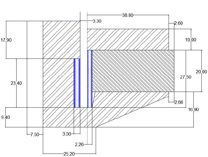
Figure 1: Geometry of SSF-082 woofer from [2].
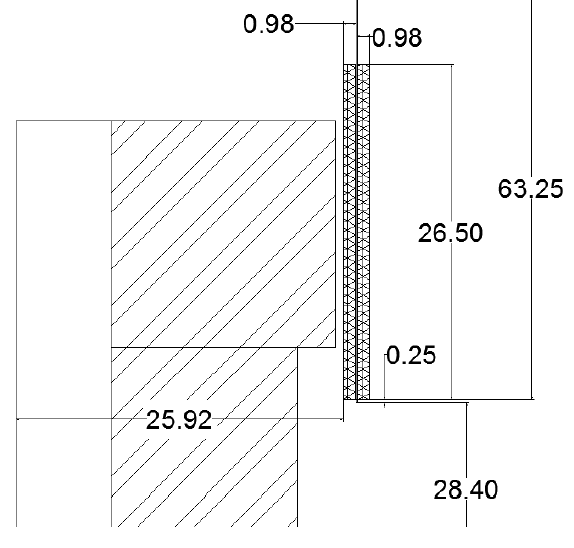
Figure 2: Detail of voice coil geometry of SSF-082 woofer from [2].
The thesis states that the magnet material is Y30 ferrite. Here, the magnet is modeled using the definition of "Ceramic 5" from the FEMM materials library, an equivalent material to Y30. FEMM's definition of Ceramic 5 is essentially the same as the 20oC curve shown in Figure 3 below.
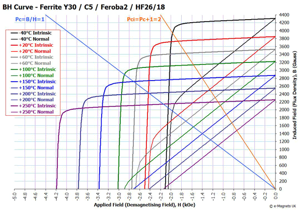
Figure 3: Demagnetization curves for Ceramic 5 / Y30 magnet material.
The magnetic circuit is specified in [2] as "low carbon steel". The model of 1018 steel from the FEMM materials library was selected as a particular and representative grade of low-carbon steel for the purposes of this example. The B-H curve is similar to the one pictured in [2], and the conductivity of 5.8 MS/m is the same is in [2]. However, the FEMM model also assumes that the low carbon steel has significant hysteresis. A hysteresis angle of 200 is defined in FEMM to account for the effects of that hysteresis in combination with eddy currents.
The wire material is specified in [2] to be 25 AWG 15% Copper Clad Aluminum (CCA) magnet wire with single-build insulation. New builds of FEMM have 10% and 15% CCA wire types, allowing computation of proximity and skin effect losses of bulk CCA windings. The conductivity of this material should be specified as the average conductivity at the temperature of interest. Specifically, at 20 degrees C, the average conductivity of 15% CCA wire is (0.15*58 MS/m + 0.85*35.09 MS/m) = 38.5265 MS/m. (Note that a 60.5% IACS conductivity for Aluminum was assumed in deriving the CCA wire type properties).
Modeling Guidance
Meshing
Since the objective in the present problem is determination of AC impedance, some guidance is needed on the selection of mesh size for iron parts subject to eddy currents. To provide that guidance, the skin depth must first be calculated. Determining the skin depth requires knowledge of the iron's magnetic permeability (\(\mu_r\)) and electrical conductivity (\(\omega\)). The skin depth, \(\delta\), can then be calculated via:
\[ \delta = \sqrt{\frac{2}{\omega \sigma \mu_r \mu_o}} \]
where \(\mu_o\) is the magnetic permeability of free space (\(4 \pi * 10^{-7}\) H/m) and \(\omega\) is frequency in radians/second.
Many speakers are made using low carbon steel for the flux path. Low carbon steel typically has a maximum relative permeability on the order of 1000. However, the maximum permeability tends to be at a fairly low flux density--a relative permeability of 500 is probably more representative of the average permeability.
A typical conductivity for low carbon steel at room temperature is the previously assumed 5.8 MS/m (same as 10% IACS conductivity).
For audio problems one is typically interested in frequencies from 20 to 20,000 Hz. The limiting case for the selection of mesh size is 20kHz. For the above material properties, the skin depth at 20kHz is 0.066 mm.
For accurate calculations of AC impedance, there must be several elements across the thickness of the skin depth region. To get an adequate meshing, a mesh size of 0.0125 mm can be defined at the surface of all low carbon steel parts.
Coil Modeling
To conveniently move the voice coil, it is suggested that all entities in the voice coil be labeled as members of Group 1. It is sufficient to model the coil as a "bulk" wound region in which each turn is not modeled. The magnet wire model in FEMM automatically includes proximity and skin effect losses.
Analysis
An analysis script was created to analyze the BL curve of the speaker and frequency-dependent inductance of the voice coil at various offsets. Both Mathematica and Matlab versions of the script are available below in the Files section, along with the loudspeaker's .FEM model. The script saves DC and AC versions of the speaker. At each displacement, the DC version is analyzed to get the DC operating point. Then, a number of AC runs are performed to get the frequency dependence for perturbations about the DC operating point.
To get a high enough mesh density to accurately resolve eddy current effects at the higher end of the audio spectrum, a mesh of nearly 200,000 nodes was required. In one test, each AC iterations take about a minute to solve, with the entire set of offsets and frequencies requiring about 2 hours. Solution time could be reduced significantly by taking fewer points per decade of frequency; considering a smaller frequency range (A 1Hz-10kHz frequency range was considered here, but 10Hz-1kHz is more consistent with the operating range of a woofer. With a 1kHz maximum frequency, a coarser surface mesh of 0.04 would be adequate.)
The BL curve computed by FEMM is shown in Figure 4. This result is essentially identical to the computed curve shown as Figure 3.20 of [2].
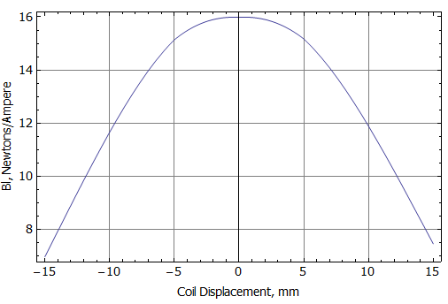
Figure 4: Plot of computed Bl curve for SSF-082 loudspeaker.
Curves of impedance and inductance versus frequency at various coil positions are shown as Figures 5 and 6. Figure 7 alternatively shows the inductance broken into an effective real-valued inductance (Leff) and an effective real-valued resistance (Reff). These graphs show that there is significant position dependence of these quantities, even though the only mechanism for the frequency dependence is eddy currents in the low carbon steel (no shorting rings are modeled in the present example). This position dependence is ultimately a contributor to distortion in the loudspeaker's output.
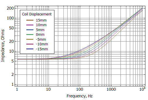
Figure 5: Blocked coil impedance vs. frequency at various coil offsets.
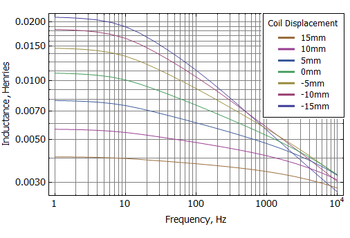
Figure 6: Blocked coil inductance vs. frequency at various coil offsets.
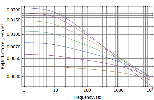
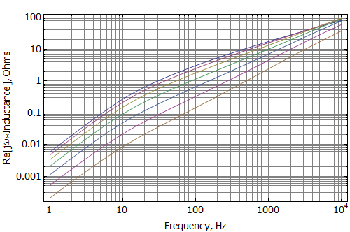
Figure 7: Blocked coil Leff and Reff vs. frequency at various coil offsets.
Conclusions
The point of this example is merely to show how impedance can be calculated vs. frequency and position using the new AC incremental formulation now included in FEMM. This formulation evaluates the AC response about a DC operating point, here established by a permanent magnet.
Futher examples may also extend the present work to show how a dynamic, time-domain model of speaker performance that includes the position- and frequency-dependent inductance variations can be regressed from the analyses performed in the present example. See TransientLoudspeaker.
Future examples (or versions of the present example) may include the effect of various shorting rings on blocked impedance.
Files
| File | Last modified | Size |
|---|---|---|
| ssf-082.FEM | 2015-11-01 12:15 | 10Kb |
| ssf-082_vs_position.nb | 2020-08-30 18:28 | 331Kb |
| ssf-082_vs_position.pdf | 2020-08-30 18:36 | 286Kb |
| ssf_082_vs_position.m | 2020-08-30 18:27 | 3Kb |
References
[1] M. Dodd, W. Klippel, and J Oclee-Brown, "Voice Coil Impedance as a Function of Frequency and Displacement", Audio Engineering Society Convention 117, Oct 2004.
[2] L. Bortot, Optimization of demodulation rings in professional loudspeakers, Masters Thesis, University of Padua, 2012.
[3] LaVoce SSF082.00L datasheet.