New Build
22Oct2023- Updated radiation boundary condition in thermal problems so that convective terms are also used, i.e. a combined radiation/convection/flux boundary can be modeled if desired. Convection bc also updated so that convection/flux can be modeled if desired.
- Updated some low-level aspects how femm and the solvers are initialized to support programmatically hiding the main window while using pyfemm in Wine.
- Patched triangle source code from vcpkg added for VS2022 compatibility. The VS2022 version of the solution points to the triangle64 directory which contains the patched code. However, the distribution executables were compiled with VS2008 using the source in the (unpatched) triangle directory for Wine compatibility.
25Jul2022
- Fixed a bug where imaginary part of a conductor voltage in current flow problems was ignored.
- Fixed bug where rotation of magnetic material is incorrect if the material is defined more than once.
- Changed installer for better silent operation
- Fixed magnetic material property definitions for some SVG wire sizes
- mi_setcomment and related ei_, hi_, and ci_ functions added to set the comment text in the problem definition.
26Jun2021
- Fixed energy integral for airgap boundary conditions. It didn't work correctly for time-harmonic problems (thanks Nicola Bianchi!)
28Mar2021 Test Build
- Fixes a couple of broken entries in the Magnetics materials library
- Changed mi_probdef and related functions so that if an out-of-range Precision is specified, the program automatically picks a reasonable value instead of throwing a cryptic error.
30Nov2020 Test Build
- Changed all calls to Triangle to use the -j flag to "jettison vertices that are not part of the final triangulation from the output .node file". This change gets rid of the spurious "singlarity flag tripped" and "can't solve the problem" messages that popped up due to orphaned nodes in the solution domain.
12Nov2020 Test Build
- Fixed vector plot problem inadvertently introduced by \( \log \left( \left| B \right| \right) \) density plot.
22Jul2020 Test Build
- Fixed SciFEMM to work with Scilab 6.1.0. (Thanks A. Tip!)
- SciFEMM bug with mi_getmaterial, ci_getmaterial, ei_getmaterial, and hi_getmaterial fixed.
- Added retries to various "fopen" instances that could occasionally fail in long batch runs.
- Changed formatting string for B-H points dialog to %.15g instead of %f so that precision of B-H curve points is not truncated.
- Minor code modifications and a new .sln file needed to compile with Visual Studio 2019. Note that release executables are still compiled with VS2008 for compatibility with WINE.
- Fixes bugs with Matlab functions hi_makeABC.m, ei_makeABC.m
- Fixed OnDraw functions so that the operating system does not think that the program is non-responsive during the drawing of density plots for solutions with lots of elements.
- Added \( \log \left( \left| B \right| \right) \) density plot for magnetics problems.
21Apr2019 Release
See Release Notes for differences with 06Oct2018. The most significant change is improvements to the thermal materials library and the magnetic materials library in the area of PM materials.
06Oct2018 Test Build
Since the "sliding band" rotor motion model was introduced in the 25Feb2018 build, FEMM has the potential to be used for transient motor simulations. Development work is presently focusing on running FEMM in Simulink, using Simscape Electrical to model external equipment connected to the machine. Versus the 25Feb2018 release build, the 06Oct2018 test build implements some fixes that were found to be necessary to enable these transient simulations:
- Fixed the cause of an occasional error that happens running many runs in Mathematica. Fkn.exe occasionally could not open a *.ans file to write over older results. The fix adds a retry if the file can't be opened.
- Fixed a bug with the computation of the "sliding band" incremental torque integral. The "previous solution" used to calculate the integral was not obtained correctly.
- For incremental runs, mesh temporary files never got deleted, leaving extra, spurious files hanging around. Code has been added to get rid of these files when they're not needed any more.
Transient Simulation
The "incremental permeability" solution type in combination with the "sliding band" rotor motion model essentially implements the hooks necessary to do transient problems using the methods described in:
E. Lange, F. Henrotte, and K. Hameyer, "An Efficient Field-Circuit Coupling Based on a Temporary Linearization of FE Electrical Machine Models", IEEE Transactions on Magnetics, 45(3):1258-1261, Mar 2009.
First, a nonlinear problem is solved at a particular nonlinear operating point (i.e. a particular set of instantaneous currents at a particular rotor orientation) Then, a linear, incremental problem based on the incremental permeabilities gleaned from the nonlinear operating point is solved for each phase where the phase of interest has a current of 1A and all other excitation is turned off. For each solution, the self inductance and the mutual inductances with all other phases are computed to generate one row of the incremental inductance matrix. Then, the "air gap interaction torque" with the full nonlinear solution is computed to determine the back EMF voltage seen by the phase of interest. The development build contains a fixed "air gap interaction torque" integral that evaluates this interaction torque in such a way that smooth results are obtained as the rotor moves, an attribute necessary for good behavior in a transient simulation.
Looking at it another way, linearizing for small changes in current, \(i\), a very general equation that describes most rotating machines is: \[ L_{inc} \frac{di}{dt} + \omega \frac{d \psi}{d\theta} + R i = v \] where \(L_{inc}\) is the incremental inductance matrix gleaned by evaluation of inductance from the incremental permeability solutions; \(\frac{d \psi}{d\theta}\) is the change in flux linkage with respect to the change in rotor orientation gleaned by the evaluation of interaction force from the incremental permeability solutions; \(\theta\) represents the rotor orientation; and \(\omega\) is the change in \(\theta\) with respect to time. Matrix \(R\) is the phase resistance matrix (which is not necessarily evaluated by FEA and should contain resistance contributions from the end turns), and \(v\) is an externally applied voltage vector.
It is possible to include a direct link to FEMM in various transient simulation engines, by wrapping the above generalized model in in the "right way".
Example Problem
For a simple example, the machine considered on the RotorMotion page (pictured below as Figure 1) can be used. The model of the machine on that page is antunes.fem. The machine is a permanent magnet brushless AC (BLAC) machine with a nominal operating point of 2hp at 2000RPM.

Figure 1: Brushless AC Motor considered on the RotorMotion page.
Perhaps the simplest transient simulation that might be performed is to model the machine running as a generator driving a balanced, three-phase load. For sanity-checking purposes, the antunes.fem machine lends itself to a pretty simple per-phase phasor model:
\[ \left( j p \omega_m L + R+R_{load} \right) i + p \omega_m \phi_m = 0 \] Parameters for the phasor model are listed in Table 1. The phase inductance was obtained by measuring the flux linkage of the B phase of the machine in the case where the coercivity of the permanent magnets was set to zero and the phase currents were set to A=-0.5A; B=1A; C=-0.5A. The resistance is the DC resistance measured for the B phase in this same simulation with a 1.314 multiplier on resistance used to account for the end turn resistance. The PM flux linkage was obtained by computing the amplitude of the fundamental component of flux linkage from the simulations shown on the RotorMotion page.
| Parameter | Symbol | Value |
| Phase Inductance | \(L\) | 4.4mH |
| Phase Resistance | \(R\) | 0.3872\(\Omega\) |
| Load Resistance | \(R_{load}\) | 6.6\(\Omega\) |
| PM Flux Linkage | \(\phi_m\) | 0.115695Wb |
| Pole Pairs | p | 4 |
| Mechanical Speed | \(\omega_m\) | 209.4 rad/s (2kRPM) |
The analytical model can be used for comparison to a Simulink model that directly calls FEMM. A Simulink model of the generator at 2000RPM driving a balanced resistive load is shown in Figure 2. The figure shows a FEMM model of the machine, but the analytical model can be substituted into this block for comparison.

Figure 2: Simulink model of PM generator driving a balanced, three-phase load.
A Level 1 Matlab S-function lives inside the FEMM Motor Model block to marshal interactions with FEMM. A Mux and a Demux separate the inputs and outputs of the S-function for easier integration into the bigger Simulink model. The S-function and Mux/Demux are shown in Figure 3.

Figure 3: S-function block used for the FEMM machine model.
In this particular implementation, the S-function has no continuous or discrete states. The S-function is used to build differential equations in terms of phase currents that are subsequently solved by Simulink. In the S-function, a call to openfemm appears in the S-function's mdlInitializeSizes that is called on start-up. During the simulation, Simulink repeatedly calls the S-function's mdlOutputs function. Here, a full nonlinear FEMM analysis determines the operating point for this iteration. Three linear incremental permeability analyses based on this nonlinear operating point determine the incremental inductance matrix and back-EMF for each phase. The function then returns \(\frac{di}{dt}\) for this present iteration, which is integrated by Simulink to get phase current. At the end of the simulation, FEMM is closed with a call to closefemm in the S-function's mdlTerminate function. As shown in Figure 4, simulations of the FEMM and analytical models give similar results. However, the FEMM model correctly resolves the on-load torque ripple due to the harmonics of the back EMF and cogging torque.
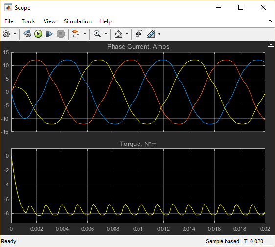 |
| FEMM Machine Model |
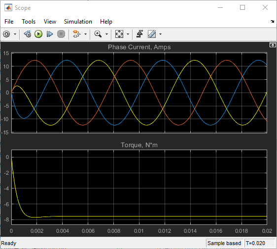 |
| Analytical Machine Model |
The same S-function used to model the machine directly in Simulink can be wrapped in a way that looks like a machine in Simscape Electrical. Then, more complicated circuits or drives could be attached (albeit with a pretty long run time in some cases). A Simulink model using Simscape Electrical components is shown below as Figure 5. For its mechanical model, Simscape blocks specify a constant rotation speed.

Figure 5: Simscape Electrical model of PM generator driving a balanced, three-phase load.
To wrap the model, a set of three controlled current sources realizes the outputs of the S-function model. Voltage measurements across the current sources provide inputs for the terminal voltage of the Simulink block. The somewhat messy wrapping of the S-function model is shown below in Figure 6.

Figure 6: Simscape Electrical model of PM generator driving a balanced, three-phase load.
Example models are in the attached SimpleTransientExample.zip. The zip file contains a FEMM version of the simulation and a version with the simple analytical model for comparison.
Future Work
Although transient simulations are now possible with FEMM, future work could increase the utility of these simulations. Possible future work could include:
- A slightly more generalized version of the S-function call is needed so that the user doesn't need to root around in the S-function code to change file names, etc., to analyze a different machine.
- Change the S-function call so that multiple instances of FEMM are used in parallel to solve the incremental analyses simultaneously.
- Nonlinear runs that start solving from a specified previous solution file. This could reduce solution times of the nonlinear solution required for each update.
- Update the formulation to include eddy currents in this transient simulation paradigm.
| File | Last modified | Size |
|---|---|---|
| SimpleTransientExample.zip | 2018-10-10 19:07 | 108Kb |
| femm42bin_arm64_22Oct2023.exe | 2023-11-26 18:28 | 16Mb |
| femm42bin_win32_22Oct2023.exe | 2023-10-22 18:16 | 8Mb |
| femm42bin_x64_22Oct2023.exe | 2023-10-22 18:15 | 10Mb |
| femm42src_22Oct2023.zip | 2023-10-22 18:15 | 3Mb |
| pyfemm-0_1_4.zip | 2023-10-22 18:19 | 17Kb |
Older Development Versions are also still available.