David Meeker
August 10, 2006
For time-harmonic magnetic problems in FEMM 4.0, windings with specified currents can be modeled, and the voltage drop across these windings can be computed as an analysis result. However, it is often the case that one would like to specify the voltage across a winding and compute the resulting current. The case of a transformer is even more difficult—one generally would like to specify a voltage across the primary of the transformer and the secondary load impedance and obtain the resulting operating currents in the transformer. The following note describes an example Octave script that uses a series of runs to iteratively determine a simple transformer’s operating point.
The single-phase isolation transformer considered in this
note is shown in Figure 1. This
particular transformer has 260 turns in the primary and 90 turns in the secondary,
reducing a 120 Vrms input on the primary to approximately 40 Vrms
across the secondary. The dimensions of
the transformer core are ![]() .
.
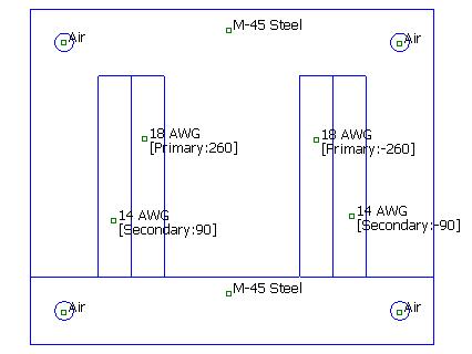
Figure 1: Single-phase EI transformer.
Although a number of interesting effects could be
considered, such as:
these effect are neglected here for the purposes of simplicity of the example. However, it can be noted that the following effects are “automatically” included by the material property definitions used in the example:
Some sort of automatic iterative method for determining the operating currents is desired. With more than one current, it is nearly impossible to tune the currents by hand to obtain a particular operating point. If the problem were linear, two equations relating the applied voltages and resulting currents could be written as:
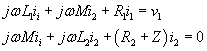
These equations correspond to the circuit diagram pictured in Figure 2:
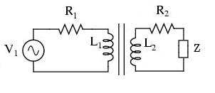
Figure 2: Transformer circuit diagram.
Resistances R1 and R2 represent the internal resistance of the transformer. Inductances L1 and L2 represent the self-inductances of the primary and secondary windings, respectively. Mutual inductance M links the two windings. The mutual inductance is closely related to the self-inductances:
![]()
where the difference between these quantities depend on the amount of leakage inductance in the transformer. Impedance Z is the load impedance attached to the transformer.
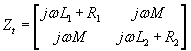
The equations could be more succinctly written in matrix notation as:
![]()
(1)
where the transformer internal impedance matrix Zt is defined as:
the load impedance matrix Zl is defined as: