David Meeker
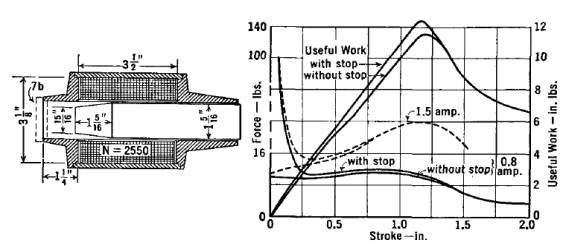
The objective of this note is to compare calculations of Force versus Position for a solenoid plunger with experimental results from Roter's "Electromagnetic Devices." In particular, the actuator pictured in Figure 1 below will be considered.
Figure 1: Roters’ Ch. IX, Fig. 7, "Taper Plunger Magnet and its force-stroke curves."
A model of this geometry is available as rotor1b.fem. The model is pictured below in Figure 2.
The actuator geometry was previously drawn in FEMM in the usual interactive mode. All components of the moving plunger were defined to be members of Group Number 1 so that the plunger can be easily selected and moved. The BH curve for the ½ hard 1020 steel was also obtained from the Roters text.
The data was stripped from the figure in Roters using WinDig, a free tool for recovering numerical data from graphs.
A combined plot, shown in Figure 2, compares the force for various plunger positions with at 1.5 A coil current as published in Roters to that predicted by the “weighted stress tensor” volume integral in FEMM. There is a reasonable agreement between the experimental and FEA results.
Figure 1: FEMM model of Roters’ “Taper Plunger Magnet”
Figure 1: Comparison of FEMM results to Roters example for 1.5 A current.