Mechanical and Electrostatic Analogies to Permanent Magnets
David Meeker
dmeeker@ieee.org
January 4, 2009
1 Introduction
For the purposes of developing an intuitive feel for the fashion in which energy is stored in a permanent magnet and its environment, it is useful to use analogies to other types of physical consideration. In this note, the magnetic circuit representation of a magnet driving an external reluctance will be reviewed. Then, capacitive and mechanical analogies to a permanent magnet will be considered. These analogies have an equivalent circuit representation that is identical to the one used to describe a permanent magnet.
2 Magnetic Circuit Representation of a Permanent Magnet
For the purposes of a magnetic circuit representation of a permanent magnet, the problem of a permanent magnet with highly permeable iron pole pieces can be considered. This geometry is pictured in Figure 1. In Figure 1, two iron pole pieces are attached to fashion the magnet into a horseshoe shape. The iron and magnet horseshoe is acting upon a thick iron wall. This problem is good for the purposes of considering energy stored the permanent magnet because all parts of the magnet are at more or less the same operating point.
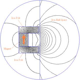
Figure 1: Permanent magnet with iron pole-pieces tugging on an iron wall.
The magnetic circuit representation of Figure 1 (derived in more detail in [1]) is shown in Figure 2.
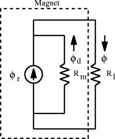
Figure 2: Circuitmodel of a permanent magnet driving load reluctance.
In the equivalent magnetic circuit, the permanent magnet is
represented by a constant flux source, ![]() , in parallel with the magnet’s internal reluctance,
, in parallel with the magnet’s internal reluctance,![]() . The reluctance
of the flux paths external to the magnet in Figure 1 (predominately the
reluctance of the air gaps between the iron poles and the iron half-plane) are
lumped together into the load reluctance,
. The reluctance
of the flux paths external to the magnet in Figure 1 (predominately the
reluctance of the air gaps between the iron poles and the iron half-plane) are
lumped together into the load reluctance, ![]() . The load flux,
. The load flux, ![]() , and the demagnetizing flux,
, and the demagnetizing flux, ![]() , can be obtained by analyzing the equivalent circuit:
, can be obtained by analyzing the equivalent circuit:
|
|
|
|
The flux source inside the magnet can neither sink nor
source power, so the energy stored in the magnet, ![]() , can be computed by considering only the energy stored
in the magnet's internal reluctance.
, can be computed by considering only the energy stored
in the magnet's internal reluctance.
|
|
3 Capacitive System Analogy
The capacitive analog to a permanent magnet driving an external reluctance is shown schematically in Figure 3. Referring to Figure 3, the insulator block with a conducting plate on top containing trapped charge is analogous to the magnet. The insulator block serves to establish a constant gap between the plate with trapped charge and the ground plane. The gap between the second, grounded, conducting plate and the plate with trapped charge is analogous to the reluctance driven by the magnet.
![]()
Figure 3: Capacitive analog to a permanent magnet.
It is common to solve electrostatic problems using an equivalent circuit
approach, similar to the way in which magnetic problems are addressed. In these
circuits, electric flux, q, is the analog of magnetic flux, ![]() , and voltage is the analog of magnetomotive force.
, and voltage is the analog of magnetomotive force.
The equivalent circuit representation of Figure 3 is shown
below as Figure 4. In this circuit, ![]() and
and ![]() represent the electric
reluctance of the insulator block and air gap, respectively. The trapped charge creates a constant total
amount of electric flux that must go to ground either through the insulator
block or through gap
represent the electric
reluctance of the insulator block and air gap, respectively. The trapped charge creates a constant total
amount of electric flux that must go to ground either through the insulator
block or through gap ![]() . By convention, positively directed flux travels upwards
in the vertical direction. The
directions of the arrows indicating the direction of positively directed flux
are pictured consistently with this convention in Figure 4.
. By convention, positively directed flux travels upwards
in the vertical direction. The
directions of the arrows indicating the direction of positively directed flux
are pictured consistently with this convention in Figure 4.
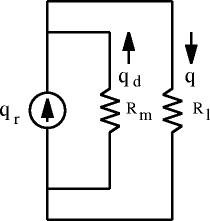
Figure 4: Equivalent circuit of electrostatic
analog.
It can now be noted that the equivalent circuit for the electrostatic system (shown as Figure 4) is identical in form to the circuit representation for a permanent magnet (shown as Figure 2). Flux travels from the plate in the negative direction through the insulator block to reach ground. This flux is analogous to the demagnetizing flux in a permanent magnet. A second flux travels upwards to the grounded plate. This flux is analogous to the load flux for a permanent magnet.
4 Planar Spring System Analogy
Although the capacitive analogy is very similar to a permanent magnet, a mechanical analogy may be superior because of its highly intuitive nature. A mechanical analogy to the energy stored in permanent magnets can be built using a system of springs.
For the spring analogy system, consider a set of three springs that have the same unloaded length. This configuration is pictured in Figure 5. Three springs are needed to create a geometrically symmetric system. Later in this note, the ends of these three springs will be joined by a rigid link. If the system is symmetric, it is intuitively obvious that a rigid link connecting all three springs will constrain the ends of all three springs to have the same vertical displacement under static conditions.
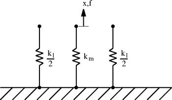
Figure 5: Array of three springs of equal unloaded length.
Next, imagine that a large, positively directed load is
applied to the center spring,![]() . This load is so
large that it plastically deforms the middle spring. After the load is released,
. This load is so
large that it plastically deforms the middle spring. After the load is released, ![]() now has a
permanent, unloaded deformation of
now has a
permanent, unloaded deformation of![]() . This
configuration is shown in Figure 6.
. This
configuration is shown in Figure 6.
The middle spring with its initial, unloaded, displacement
is an analog to a permanent magnet for the purposes of stored energy.
Furthermore, the energy expended in plastically deforming the spring to impose
its unloaded displacement is directly analogous to the magnetization process
for a permanent magnet—some energy has to be sunk into the “magnet” for the
purposes of forming it. However, the
energy used to create the “magnet” is never stored; it is dissipated as
heat. In this case, the dissipated
energy is associated with the plastic deformation of steel; in a magnet, this
energy is associated with lining up all of the magnetic domains inside the
magnet. When the “magnetizing force” is
released, there is no energy stored in![]() .
.
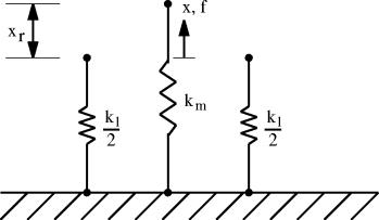
Figure 6: Array of three springs after the middle spring has been plastically deformed, adding a permanent initial displacement of ![]() .
.
Lastly, imagine that the ends of all three springs are
connected together by a rigid link so that the endpoints of all the springs are
constrained to be at the same value of displacement,![]() . This configuration
is shown in Figure 7.
. This configuration
is shown in Figure 7.
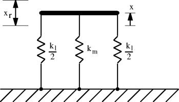
Figure 7: All three springs are attached to a rigid link.
The configuration shown in Figure 7 is amenable to standard solution methods for mechanical problems. Specifically, all of the forces on the rigid link have to add up to zero for the rigid link to be in static equilibrium. The sum of the forces can be written as:
|
|
where ![]() is the force on
the link from the center magnet, and
is the force on
the link from the center magnet, and ![]() is the force on
the link from the outboard magnets. It
is assumed that the springs are linear, and the relationships between force
applied to the end of the springs and the resulting displacements of the ends
of the springs are:
is the force on
the link from the outboard magnets. It
is assumed that the springs are linear, and the relationships between force
applied to the end of the springs and the resulting displacements of the ends
of the springs are:
|
|
(5) |
|
|
(6) |
Substituting the equations for spring force into (4) yields the following for the balance of force on the rigid link:
|
|
(7) |
which can solved
for ![]() :
:
|
|
The movement of the
end of the center spring from its unloaded position can be denoted by the
symbol ![]() . The displacement of
the center spring is:
. The displacement of
the center spring is:
|
|
Now, it can be noted that the expressions for ![]() and
and ![]() in (8) and (9) have exactly the same form as the expressions for
load flux,
in (8) and (9) have exactly the same form as the expressions for
load flux, ![]() , and demagnetizing flux,
, and demagnetizing flux, ![]() , presented as (1) and (2). A spring
with an offset in its initial position is a perfect analog mathematically for
the operation of a permanent magnet.
The mechanical system consisting of springs can even be represented by
an equivalent circuit model (pictured in Figure 8) that is identical to the
magnetic circuit model for a permanent magnet (shown as Figure 2).
, presented as (1) and (2). A spring
with an offset in its initial position is a perfect analog mathematically for
the operation of a permanent magnet.
The mechanical system consisting of springs can even be represented by
an equivalent circuit model (pictured in Figure 8) that is identical to the
magnetic circuit model for a permanent magnet (shown as Figure 2).
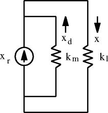
Figure 8: Equivalent circuit model of Figure 7.
5 Conclusions
This paper has developed mechanical and electrostatic analogs to a permanent magnet. The purpose of presenting these analogs is to allow the intuitive insight available in the analysis of mechanical and electrostatic systems to be applied also to permanent magnets.
For a permanent magnet, a constant flux source allows energy to be stored in the absence of an externally applied magnetomotive force. The analogy systems behave in a similar way, i.e. for the electrostatic analog, trapped charge allows energy to be stored in the absence of an externally applied voltage, and for the mechanical analog, an initial position offset in a spring allows energy to be stored in the absence of an externally applied force.
In the analogy systems, it seems intuitively clear that a position offset or a trapped charge are, in themselves, not sources or sinks of energy. In the systems considered, all changes in energy are due to mechanical work performed on the system by some external agent (e.g. a hand attaching the ends of the springs to the rigid link in the mechanical example). Similarly, permanent magnets are also passive elements.
References
[1] D. Meeker, “Magnetic Circuit Derivation of Energy Stored in a Permanent Magnet,” http://www.femm.info/wiki/PMEnergy.