Radial Magnetization
Introduction
In most cases, permanent magnet regions are defined with a constant magnetization direction for the entire region, as described in the Permanent Magnet Example. However, especially for the case of surface-mount permanent magnet motors, a magnetization direction that varies throughout the volume is desired. Specifically, one sometimes desires to define a radial magnetization direction. The purpose of this note is to explain how to define a radial magnetization direction in FEMM.
Diametral Magnetization
Example file: diametral_magn.fem
In many machines with arc-shaped magnets, it is sufficient to simply define the magnetization direction to be constant. However, for arcs that cover a large angle, there can be a significant difference between a constant magnetization direction (i.e. "diametrial magnetization") or a magnetization direction that varies so that the magnetization is always pointed directly across the air gap (i.e. "radial magnetization"). Figure 1 shows a machine with permanent magnets that cover an 80o arc. In this example, a constant magnetization direction is defined for each magnet. At the edges of the magnet, the constant magnetization direction results in magnetization that is nearly diagonal with respect to the gap. Depending on how the magnets are manufactured, this may be a true or erroneous representation of the field--the magnets need to be modeled as magnetized.
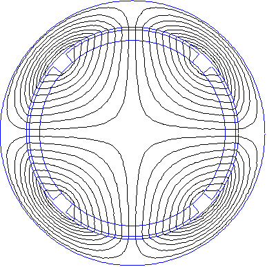
Figure 1: Diametral Magnetization Example
Radial Magnetization
Example file: radial_magn.fem
A radial magnetization direction can be defined in two ways:
- Approximate a radial magnetization by breaking the large arc into a number of smaller magnets. Each smaller magnet is then defined with a slightly different magnetization direction depending on its position withing the arc.
- Exactly model a radial magnetization scheme by defining the magnetization direction as a function, rather than as a constant.
This section focuses on the second approach. For the purposes of defining magnetization direction, equations can be written that employ the variables x, y, r, and theta. To define an outward radial magnetization direction, simple define the Magnetization Direction to be theta in the Block Label Properties dialog, as shown in Figure 2. To define an inward radial magnetization, define the magnetization direction to be theta+180.
Figure 2: Block Label Properties defining a radial magnetization direction.
Figure 3 show the results of redefining the magnetization direction to be radial in the same example geometry used in Figure 1. Now, the magnetization is directed radially across the gap, even at the edges of the magnets.
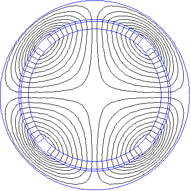
Figure 3: Radial Magnetization Example
Other Possibilities
Example file: Halbach.fem
As noted above, theta is not the only variable available for use in the magnetization definition. Another possibility is the definition of a Halbach Array magnetization pattern. Usually, Halbach arrays are built out of a set of rectangular magnets, each with a constant magnetization direction. However, the same idea (a magnetization scheme that concentrates the flux on one side of the array) with a continuous magnetization pattern. To create a Halbach magnetization pattern, define the magnetization direction to be 180*x/PolePitch where a number should be inserted for PolePitch. In the example file, the pole pitch is 1", so the magnetization direction is defined as 180*x. The solution for the example problem is shown below in Figure 4. All flux is external to the magnet is concentrated on the top side of the array.
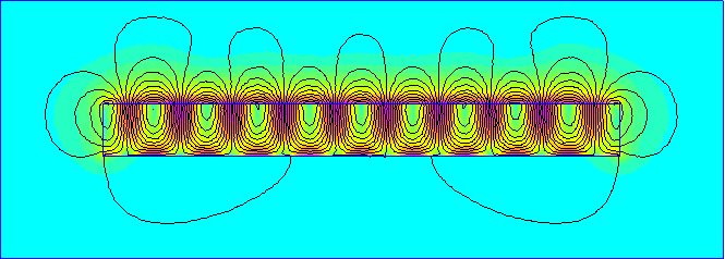
Figure 4: Halbach Magnetization Example
Conclusions
This example has shown how magnetization direction can be defined as a function rather than as a constant value. The most common application for this capability is the definition of a radial magnetization direction in surface-mount PM motors/generators. However, other magnetization schemes like a linear Halbach magnetization pattern can also be defined.