Coreless Three-Phase Alternator
José Borges de AlmeidaUniversidade do Minho
Physics Department
josebda@gmail.com
30Mar2021
Introduction
This note describes the modeling of an alternator for a small wind turbine; the rated power is about 500 W, at 1800 rpm, and it presents no cogging or starting torque, meaning that it will start rotating even with the tiniest breeze. Most permanent magnet alternators are classified as either inner or outer rotor, but the present one is both inner and outer rotor; the windings are embedded in a cylindrical resin casting, which sits between two layers of rotating arc shaped magnets, custom made for the purpose. Fig. 1 shows how the radially magnetized magnets are disposed on a double layer with the coils between them.
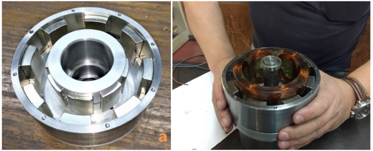
Fig.1 Rotor with double layer of magnets (left), resin embedded coils sit between the magnets' layers (right).
This coreless design has constant reluctance, which avoids de need for laminations and completely eliminates cogging; purpose made magnets, on the other hand, may be difficult to get hold off and may be expensive, if purchased in small quantities. Further details about the prototype design and construction are available in a technical article, soon to be published in a special issue of Energies, going under the title “Electrical Machine Design 2020”.
The Octave script
The first section, in Fig. 2, defines the main parameters. The script is very versatile but in no way foolproof, it is possible to use it for different designs but one may encounter situations where it produces an error and the user may need to make adaptations. In this section wireType is set to a non-standard diameter of 1.79 mm; in fact, the windings were made with 5 wires of 0.8 mm diameter, producing a total cross-sectional area equivalent to one wire of 1.79 mm diameter. This type of wire doesn't exist in the Materials Library and is added further down in the script; note also the magnetLength equal to 40 mm, used in mi_probdef(0,units,"planar",1E-8,magnetLength) to set the problem depth.
In the section Draw inner and outer shells, the two steel cylinders are drawn and their properties set. A long section of the script draws all the inner and outer magnets an sets their properties. In each case, just one magnet is drawn and then it is cloned around the circumference; the full set of magnets is set to group 1 for convenience.
The section Draw the windings starts with a calculation of the number of coils in numberbob = 3 *numberpp * bobbinReduce; the last factor was set in the parameters' definitions as 0.5, but it could also be set to 1. For ease of construction it is easier to have just 6 coils rather then 12. The windings are drawn as trapezoids with curved ends and not with their exact shape; the set of windings constitutes group 2.
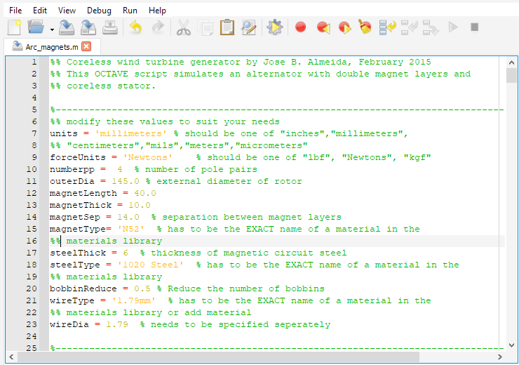
Fig.2 Parameter definition
Fig.3 shows the section where two winding legs are selected and attributed to Phases A and B, one with current going into the drawing and the other one coming out; the process is then repeated for all the winding legs; the final result is shown in figure 4. The following section saves the design in windgen.FEM and opens FEMMresult.txt as a text file to receive the main design elements for reference; the contents of this file are as follows:
• Number of pole pairs = 4
• Magnet type = N52
• Outer diameter = 145 millimeters
• Inner diameter = 53 millimeters
• Magnet l x t = 40 x 10 millimeters
• Outer magnet arc = 25.000000 degrees
• Outer magnet radii = 66.500000, 56.500000 millimeters
• Inner magnet arc = 33.235294 degrees
• Inner magnet radii = 42.500000, 32.500000 millimeters
• Number of bobbins = 6
• Bobbin thickness = 13.200000 millimeters
• Width of bobbin core = 28.7132 millimeters
• Wire diameter = 1.790000 millimeters
• Number of turns = 32
• Induction amplitude = 0.716094 Tesla
Section Start processing analyses the design and plots flux density, as shown in Fig. 5; it also creates an Octave plot of the radial flux density in an arc half way between the two magnet layers, Fig. 6; the plot adds an sinusoidal curve, for comparison; here the script ends.
In a previous version there was a section which tried to evaluate the electrical characteristics of the windings. It did this by replacing steel by air in all the magnets and energizing Phase A; the circuit resistance and inductance could then be taken. These results were not very meaningful, especially the inductance. Since the coils have dielectric core, a very low inductance is expected but, because the inductance is so low, the distributed capacitance cannot be neglected; in the accompanying Mathematica script the internal reactance is set to zero and this was found consistent with the test results.
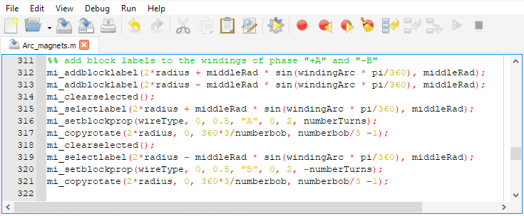
Fig. 3 Setting parameters for two winding legs: Phase A and Phase -B
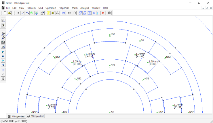
Fig. 4 The final design.
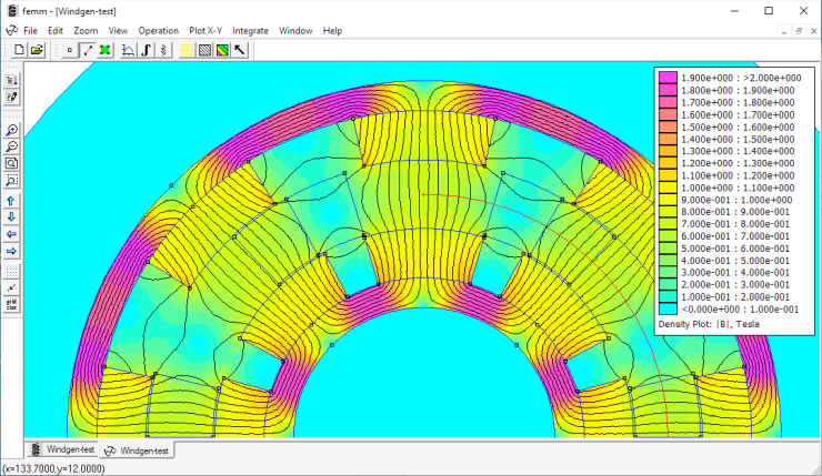
Fig. 5 Flux density plot.
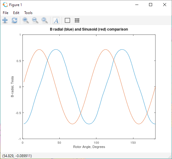
Fig. 6 Radial flux density compared to a sinusoid; the closeness of the two curves warrants the use of the latter
in calculations.
The Mathematica script
A Mathematica script is included in the download, which uses data adapted from the FEMM model to create an equivalent electric circuit of the alternator; it uses the fact that the radial flux density variation with angle or time is very nearly sinusoidal to evaluate integrals and derivatives and reduces the flux density amplitude taking in consideration a variation across the inter magnet gap; some adjustments were made after confrontation with the prototype test results.
Fig. 7 summarizes the electrical model output and Fig. 8 plots the maximum attainable power, with safe limit lines for peak power (green) and sustained power (red). The generator equivalent circuit is described by a generator constant KG = 8.3 mV/rpm and internal resistance Ri = 49.6 m\(Ω\).
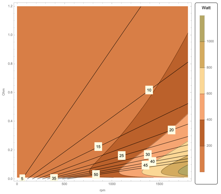
Fig. 7 Summary of alternator characteristics; the black lines represent load current.
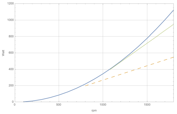
Fig. 8 Maximum power vs. rotation speed; safe limit lines for peak power and sustained power.
| File | Last modified | Size |
|---|---|---|
| Arc_magnets.m | 2021-04-01 07:24 | 18Kb |
| Windgen-arc-mag.nb | 2021-03-31 19:24 | 61Kb |
| Windgen.pdf | 2021-04-01 07:04 | 5Mb |