Loundspeaker Driver Dynamics
David Meeker
dmeeker@ieee.org
07Sep2015
Introduction
The purpose of this page is to describe how FEMM can be used to analyze the small signal properties of a loudspeaker driver. With FEMM, the effects of eddy currents and/or shorting rings can be included in the small signal model.
This note will first discuss a model of a loudspeaker that is consistent with the Thiele/Small Model. Then, the note will discuss modifications to this model to include more complicated electrical behavior identified by incremental permeability AC simulations in FEMM.
Baseline Loudspeaker Model
It is assumed that the loudspeaker is driven by a voltage source with no output impedance. This is a reasonable assumption for audio amplifiers--the load impedance is typically at least 10X the output impedance of the amplifier (see wikipedia/Output_impedance).
The loudspeaker's mechanical dynamics might be simply modeled as the spring-mass-damper system pictured in Figure 1. It is assumed that the mass, \(m\) has the mass of the air moved by the cone rolled in, along with the moving mass of the loudspeaker (cone, voice coil, dust cap). The stiffness, \(k\), is the spring constant of the spider. The damping, \(c\), is mostly due to the surround and to the spider itself--damping due to the air is usually neglected, because it is comparatively small.
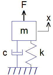
Figure 1: Spring-Mass-Damper system representing loudspeaker mechanical dynamics
In Figure 1, force \(F\) is due to the action of the voice coil. For small displacements, the force due to the voice coil is proportional to the current carried by the coil:
| \[ \large F = K_F i \] | (1) |
| \[ \large m \ddot{x} + c \dot{x} + k x = K_F i\] | (2) |
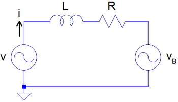
Figure 2: Inductor-Resistor circuit representing loudspeaker mechanical dynamics
Figure 2 shows amplifier voltage \(v\) driving the inductance, \(L\), and resistance, \(R\) of the voice coil, pushing against the back-EMF voltage, \(v_B\), that arises due to the motion of the voice coil. From the mechanical system, the power applied to the mechanic system from the voice coil is the product of force and velocity:
| \[ \large P_{mech} = F \dot{x} = k_F i \dot{x}\] | (3) |
| \[ \large P_{elect} = v_B i\] | (4) |
| \[ \large P_{mech} + P_{elect} = 0\] | (5) |
| \[ \large v_B = - K_F \dot{x} \] | (6) |
| \[ \large L \frac{di}{dt} + R i = v - K_F \dot{x}\] | (7) |
| \[ \large \left(s L + R \right) i = v - s K_F x\] | (8) |
| \[ \large \left( s^2 m + s c + k \right) x = K_F i\] | (9) |
| \[ \large x = \left( \frac{k_F}{s k_F^2 + \left( s L + R \right) \left( s^2 m + s c + k \right)} \right) v \] | (10) |
| \[ \large i = \left( \frac{s^2 m + s c + k}{s k_F^2 + \left( s L + R \right) \left( s^2 m + s c + k \right)} \right) v\] | (11) |
| \[ \large Z = \frac{v}{i} = \frac{s k_F^2}{s^2 m + s c + k} + \left( s L + R \right) \] | (12) |
Connection to Thiele-Small Parameters
Additional References
A. N. Thiele, Loudspeakers in vented boxes: Part I, Journal of the Audio Engineering Society, 19(5):382-392, 1971.
A. N. Thiele, Loudspeakers in vented boxes: Part II, Journal of the Audio Engineering Society, 19(6):471-483, 1971.
https://en.wikipedia.org/wiki/Thiele/Small