
Inductance Calculation Example
David Meeker
Companion file: induct1a.fem
Introduction
A common task that FEMM might be applied to is the calculation of the inductance of a gapped inductor. Although the inductance can be estimated using simple magnetic circuit theory, the circuit approach typically ignores flux leakage and fringing effects. To resolve these non-ideal effects in more detail a finite element analysis can be employed. The goal of the present example is to show how inductance is calculated in FEMM simulation and to compare that result to the approximation obtained through a magnetic circuit approach.
Example Geometry
The example geometry is composed of a gapped, laminated EI core with the cross-section as pictured in Figure 1. An E core with a center pole 0.5" wide and outer poles 0.25" wide is separated from an I-shaped return path by an air gap 0.025" thick.
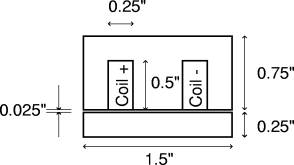
The winding that lies in the slots of the E consists of 66 turns of 18 AWG wire heavy build insulation, for approximately a 66% copper fill fraction in the coil window. It is assumed that the core extends for 1 inch in the into-the-page direction. For the purposes of this model, the material is assumed to be a linear ferromagnetic material with a relative permeability of 2500.
Circuit Theory Inductance
For a rough approximate of inductance, we can assume that there is no leakage and fringing, and that the contribution of the iron sections to the reluctance of the magnetic circuit is trivial in comparison to the contributions from the air. Then, the flux flowing in the magnetic circuit is obtained by solving the circuit equation:
forφ, the total flux linked by the coil. The R represents the reluctance of the magnetic circuit, which under our assumptions can be written as:
where g = 0.025", apole = 0.5 in2, and μo = 4π(10-7) H/m. Since the total flux linking the coil is then:
and the total self-inductance is just that flux times the total number of turns:
so that the self-inductance is:
Since, in our case, there are 66 turns, the inductance works out to be:
We would expect the inductance derived from finite element computations to be in the neighborhood of 1.39 mH.
Finite Element Inductance (I)
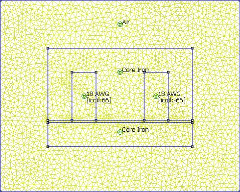
For the purposes of creating a finite element solution, the inductor is placed at the center of a 2" by 2.5" box. On the boundaries of the domain, a boundary condition of A=0 is defined. For the purposes of performing the finite element analysis, a current of 1 A is somewhat arbitrarily applied to the coils. A fairly coarse mesh density with the mesh size constrained to be no larger than 0.05" is defined everywhere. The meshed problem domain is pictured in Figure 2.
Once the analysis is performed and the postprocessor is run,
the inductance can be derived by pressing the Circuit Properties button in the
post-processor:![]() A dialog appears with a number of properties
of the winding as seen from the winding terminals. The Circuit Properties dialog
for this example is shown below in Figure 3.
A dialog appears with a number of properties
of the winding as seen from the winding terminals. The Circuit Properties dialog
for this example is shown below in Figure 3.
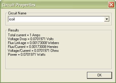
In the absence of permanent magnets or other coils, “Flux/Current” result can be interpreted directly as self inductance:
This result is higher than the 1.39 mH predicted by the simple circuit theory approach because the leakage and fringing effects neglected in the circuit approach tend to raise the inductance slightly.
Finite Element Inductance (II)
An alternative approach is to obtain energy via the "Magnetic Field Energy" integral. For this approach, energy is obtained via:
where this integral is taken over the entire problem
domain instead of just over the coils. To perform this integration in the
postprocessor, switch to block integral mode by pushing the ![]() button on the task bar. Then, select each region in the problem via
left mouse button clicks. When the
entire problem region is selected, push the Integral button and select the
“Magnetic Field Energy” integral from the drop list of volume integrals. If W
represents the integral result, the resulting inductance is:
button on the task bar. Then, select each region in the problem via
left mouse button clicks. When the
entire problem region is selected, push the Integral button and select the
“Magnetic Field Energy” integral from the drop list of volume integrals. If W
represents the integral result, the resulting inductance is:
For the example problem, the result from the energy integration is:
Which, when substituted into the formula, yields the same result as method (I):
Conclusions
A simple example has been presented that demonstrates how FEMM can be used to obtain inductance. A 2D planar problem was considered, and inductance results from two methods were compared with one another and with a "sanity check" inductance estimate from magnetic circuit theory.
Although the results from the two finite element approaches to deriving inductance are identical in this case, it is usually better to use method (I). The reason is that some boundary conditions (i.e. the asymptotic boundary condition used for approximating an "open boundary" problem) imply that some energy is stored outside the modeled problem domain. Internally, FEMM calculates the flux linkage using a method that accounts for this additional energy, whereas integrating B×H over all elements does not.
Strictly speaking, a single inductance coefficient implies a linear relationship between applied current and resulting flux. For this reason, an example problem with only linear materials was considered.
If the problem has nonlinear materials and there is significant saturation, there is no longer a linear relationship between current and flux. However, there are many situations in which a sinusoidal current is applied, and one would like to know the amplitude of the fundamental of the flux corresponding to the applied current. In this case, a harmonic analysis can be run in FEMM (i.e. when a frequency other than zero is specified in the Problem Definition). FEMM implements a nonlinear time harmonic formulation that computes the amplitude and phase of the fundamental portion of the magnetic field for time harmonic problems with nonlinear materials problems. For nonlinear time harmonic problems, the Circuit Properties dialog can again be used to harvest a coil’s various terminal properties.