Analysis of an Interior Permanent Magnet Motor
Introduction
A good example EV motor design is presented by Pellegrino et al. in [1]. This analysis will consider the IPM described in [1] to see if similar performance predictions are gleaned.
Stated Model Geometry
Some geometric parameters are quoted in the paper, but others were deduced from drawings in the paper, shown here as Figure 1.
c
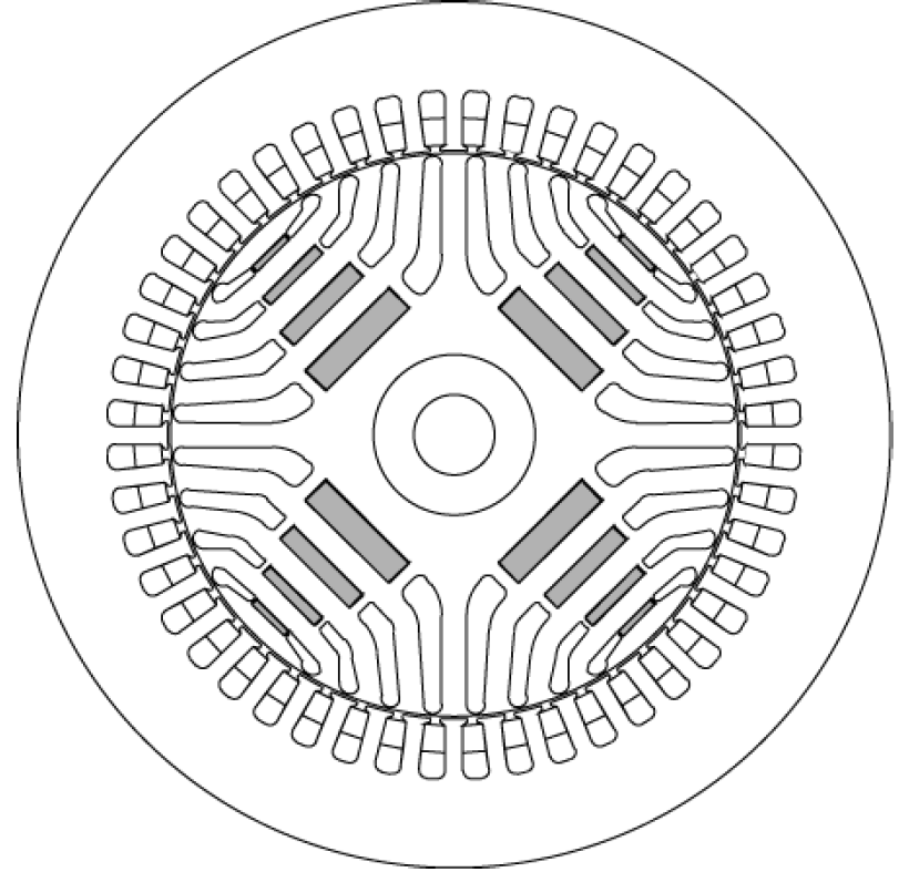
Figure 1: Interior permanent magnet motor pictured in [1].
Stated dimensions / attributes of the machine are (from Table I of [1]):
- Pole Pairs: 2
- Stator OD: 216 mm
- Stator ID: 142 mm
- Stack Length: 170 mm
- Air Gap: 0.7 mm
- Number of Turns: 20
- Copper Fill Factor: 0.4
- End Connection Length (per side): 150 mm
- Assumed Rotor Temperature: 150oC
- Assumed Stator Temperature: 130oC
- Steel Grade: M250-35A (3% Si-Fe, 0.35 mm thick -- essentially identical to 29 gauge (0.014") M-19)
- Magnet Grade: BNM-42SH (Essentially the same as Arnold N42SH)
Assumed Attributes
Some necessary attributes of the machine weren't described in the paper. The following assumptions were made:
- Stacking Factor: 0.95 (based on rules-of-thumb tabulated6 on the StackingFactor page)
- Wire Size: 22 AWG wire (0.6438mm in diameter) wound 9 "in hand". That is, each turn consists of 9 strands of 22 AWG in parallel. This stacks up to a copper fill factor of approximately 0.4.
- Winding Scheme: A winding short-pitched by two slots was assumed. Drawing out this winding scheme for two poles worth of slots looks like:
| A+ | A+ | A+ | A+ | B- | B- | B- | B- | C+ | C+ | C+ | C+ | A- | A- | A- | A- | B+ | B+ | B+ | B+ | C- | C- | C- | C- |
| A+ | A+ | B- | B- | B- | B- | C+ | C+ | C+ | C+ | A- | A- | A- | A- | B+ | B+ | B+ | B+ | C- | C- | C- | C- | A+ | A+ |
This pattern yields a stator MMF with the lowest possible harmonic content, given a 48-slot, 4-pole stator.
Presumably, the "20 turns" in the winding is to be interpreted as 20 turns per pole per phase. If we drew out the 24 slot / 2 pole winding pattern again, we could represent the turns around one pole in red and the turns around the other pole in blue.
| A+ | A+ | A+ | A+ | A- | A- | A- | A- | ||||||||||||||||
| A+ | A+ | A- | A- | A- | A- | A+ | A+ |
There are four half-slots for each side of the coil that make up the 20 turns, so there must be 5 turns per half-slot.
Derived Attributes
To account for the 130oC stator temperature, assuming a 39.3%/100oC temperature coefficient of resistance, the conductivity of the copper wire, \(\sigma\), would be
\[ \sigma = \frac{58 \,\mbox{MS/m}}{1+0.00393/^{^\circ} \mbox{C}*(130^{^\circ}\mbox{C} - 20^{^\circ}\mbox{C})}= 40.4943 \, \mbox{MS/m} \]
To account for the extra end turn length, an additional scaling factor was applied to the conductivity to yield effective conductivity, \(\sigma_{eff}\)
\[ \sigma_{eff} = 40.4943 \,\mbox{MS/m} * \frac{170 \,\mbox{mm}}{170\,\mbox{mm} + 150 \,\mbox{mm}}= 21.5126 \, \mbox{MS/m} \]
FEMM Model
Detailed slot, magnet, and flux barrier geometry was gleaned by digitizing Figure 1 with ScanIt. The resulting FEMM model is available in the "attachments" list at the bottom of this page.
|
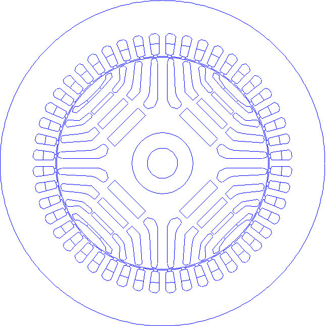 |
Figure 2: Original vs. Re-created Geometry.
Disconnects from [1]
Parallel Poles?
Evaluating the geometry, FEMM computes a phase resistance is 0.43155 Ω, whereas the stated phase resistance is 0.027 Ω. The computed resistance is almost exactly a factor of 16 bigger than the quoted resistance. Although it is not addressed in the paper, the four poles must be connected in parallel for the entire machine to have the quoted resistance.
Torque vs. Current Issues?
The quoted Continuous Torque of the machine is 160 N*m at a phase current of 255 Apk. The phase angle at which the currents are driven to produce this torque is not given, but this is called the "Maximum Torque per Amp" (MTPA) operating point. It makes sense that the angle should be selected to maximize torque. To determine a good angle for producing torque, a Mathematica script was written to step through current phase angles at 10-degree increments:
<< c:\\femm42\\mathfemm\\mathfemm.m
OpenFEMM[]
OpenDocument[NotebookDirectory[] <> "PellegrinoIPM.fem"];
MISaveAs["c:\\temp\\temp.fem"];
tt = {};
For[k = -180, k <= 180, k += 10,
imax = 255/4.;
MISetCurrent["A", imax*Cos[k*Degree]];
MISetCurrent["B", imax*Cos[(k - 120)*Degree]];
MISetCurrent["C", imax*Cos[(k + 120)*Degree]];
MIAnalyze[1];
MILoadSolution[];
MOGroupSelectBlock[1];
tq = MOBlockIntegral[22];
tt = Append[tt, {k, tq}];
Print[k, " ", tq];
]
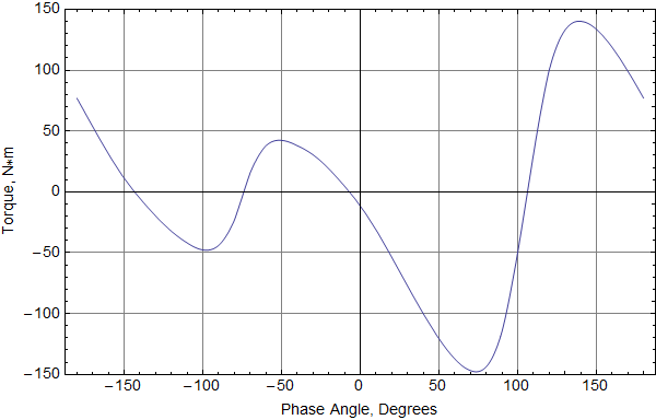
The torque graph should be symmetric, but it is skewed to one side because of cogging torque. Taking the average of the peaks gives a torque of 144 N*m for a 255A<sub>pk</sub> current--about 10% lower than the quoted 160 N*m.
If the scanned geometry does not match the geometry analyzed in [1], too much flux may be leaking around the barriers, somewhat reducing the output torque.
References
[1] G. Pellegrino et al., "Comparison of induction and PM synchronous motor drives for EV application including design examples", International Conference on Electrical Machines (ICEM) 2010, Rome, 6-8 Sept. 2010.
| File | Last modified | Size |
|---|---|---|
| PellegrinoIPM.FEM | 2015-02-08 13:37 | 73Kb |