Circuit Model of a Tape-Wound Toroid
Introduction
Tape-wound toroids are constructed by wrapping a long tape of lamination material into a toroid, as shown in Figure 1. When wrapped with a current-carrying winding, magnetic flux flows around the ring. However, there is no continuous flux path that the flux can take round the ring, since the tape has a discrete beginning and end. At some point, flux must cross the thin air gap between successively layers of the tape to complete its loop.
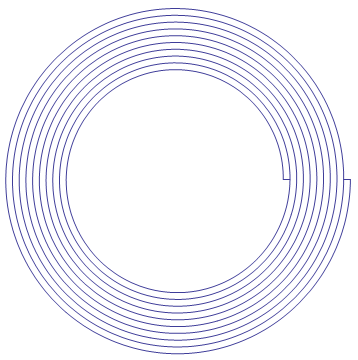
Figure 1: Tape-wound toroid.
Because part of the flux path travels through air, the bulk reluctance of the ring must be at least a bit higher than if it were composed of flat washer (where flux could unambiguously stay in iron for the entire circuit around the toroid). The purpose of this note is to derive a simple circuit model of a tape-wound toroid that brings the additional reluctance due to tape winding clearly into evidence.
Analysis
For ease of analysis, consider an alternate realization of a tape-wound core, as pictured in Figure 2. This tape-wound core has the iron tapered in the inner- and outer-most layers so that the core has a constant inner radius of \(R_i\) and a constant outer radius of \(R_o\).

Figure 2: Alternate realization of a tape-wound core with tapered start and finish.
To simplify the analysis, this domain could be "unrolled" as shown in Figure 3. The laminations of the unrolled domain are not exactly aligned with the domain. They are located at a small angle,\(\phi\), relative to the domain. Angle \(\phi\) is closely approximated as:
\[ \phi = \frac{R_o-R_i}{n \pi \left( R_o +R_i \right) } \]
where there are \(n\) layers of tape in the core.
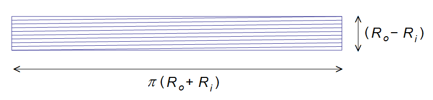
Figure 2: "Unrolled" tape-wound core.
Consider a reference frame aligned with the laminations in the core and assume that the core iron has a constant permeability of \(\mu\). The laminated structure could be replaced by a bulk region with a permeability of \( s \mu \) in the "easy" direction and \(\mu_o / (1-s) \) in the "hard" cross-lamination direction, where \(s\) represents the stacking factor of the material. Stacking factor varies depending on lamination thickness (see StackingFactor); however, a fairly typical tape-wound lamination thickness is 0.004" with an associated ~0.90 stacking factor.
For the unrolled domain, flux must traverse the bulk domain along purely radial flux paths, since there's no place for the flux to travel axially. The permeability tensor, transformed to a reference frame aligned with the unrolled Figure 3 domain is:
\[ M = \left[ \begin{array}{cc} \cos \phi & \sin \phi \\ -\sin \phi & \cos \phi \end{array} \right]
\left[ \begin{array}{cc} s \mu & 0 \\ 0 & \mu/(1-s) \end{array} \right]
\left[ \begin{array}{cc} \cos \phi & -\sin \phi \\ \sin \phi & \cos \phi \end{array} \right]
\]
However, to get the MMF drop around the ring for a given flux density, the inverse of \(M\) is required:
\[ H = M^{-1} B \]
Since the only non-zero component is the radially directed component, and with much simplification from Mathematica:
\[ H_r = \left( \frac{\cos^2 \phi}{s \mu} + \frac{(1-s) \sin^2 \phi}{\mu_o}\right) B_r \]
It can futhermore be noted that angle \(\phi\) is expected to always be very small, such that:
\[ H_r \approx \left( \frac{1}{s \mu} + \frac{(1-s) \phi^2}{\mu_o}\right) B_r \]
The total MMF drop around the ring can be obtained by multiplying by \(L\), the total length of the unrolled core (\(L=\pi(R_o+R_i)\)).
\[ \Delta MMF = \left( \frac{L}{s \mu} + \frac{(1-s)L \phi^2}{\mu_o}\right) B_r \]
The first term can be interpreted as MMF drop over the iron, and the second term can be interpreted as the MMF drop over an effective air gap, \(g\), in the core. If the MMF drop over the effective air gap is \(g/\mu_o\), by comparing this MMF drop to the second term, it can be concluded that the effective air gap due to the portion of the flux that must travel across the air gap between lams is:
\[ g = \frac{(1-s)(R_o-R_i)^2}{ n^2 \pi (R_o+R_i)} \]
To give this air gap formula a frame of reference, a core could be considered that has an outer radius of 1", and inner radius of 0.5", a fill factor of 0.9 with 112 layers of iron. In this case, the equivalent gap is approximately 0.4 µin.
Conclusions
A formula for the equivalent air gap of a tape-wound core. For realistic core dimensions and tape thicknesses, the equivalent air gap length is very small. Since the gap is so small, it is reasonable to neglect the gap in most calculations. However, for thicker tapes and nickel cores with very high permeability, the air gap size could be relevant.