(Anti)Periodic Air Gap Boundary Condition Torque Benchmark
David Meeker
dmeeker@ieee.org
25Feb2018
1 Introduction
The 25Feb2018 test build of FEMM has "air gap boundary condition" that allows rotor motion to be modeled without changing the rotor or stator meshes. To assess the accuracy of the resulting torque, a benchmark with a closed-form solution is of value. Here, the torque on a dipole in a uniform magnetic field will be computed for various rotor angles. This problem has a simple closed-form solution that is readily compared to FEMM results.
2 Problem Description
A bar magnet is considered that measures 1cm long and 0.5cm wide, extending 2cm in the "into-the-screen" direction. It is assumed that the magnet has an internal relative permeability of 1 and a coercivity (\(H_c\)) of 1 MA/m, similar to a 40MGOe rare earth magnet.
The strength of the magnet's dipole moment, \(\bf m\), is straightforward to calculate:
\(|{\bf m}| = H_c V\) = 1 A*m2
where \(V\) is the volume of the magnet.
The bar is placed in uniform magnetic field, \({\bf B}_{ext}\), with a 1T magnitude. The torque on the dipole is:
\(\tau = {\bf m} \times {\bf B}_{ext}\)
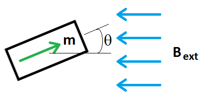
Defining angle \(\theta\) as per Figure 1:

Figure 1: Problem definition for torque on a dipole.
the expression for torque for the problem of interest reduces to:
\(\tau = (\)1 N*m\() \sin \theta \)
3 Finite Element Model
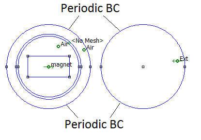
A uniform magnetic field in an unbounded space can be modeled in finite elements using the "Kelvin Transformation" (see, for example, DOI: 10.1109/20.92293). It can be shown that a circular domain surrounded by unbounded space is exactly equivalent to a circular domain linked to another circular domain with periodic boundary conditions. Using the Kelvin Transformation, a uniform magnetic field in the domain of interest can be obtained in a domain by filling the circle representing the exterior with a permanent magnet material with \(H_c = 2 |{\bf B}_{ext}|/\mu_o\).
To investigate rotor motion modeled by an air gap boundary condition, an annular region can be defined around the magnet. The inside of the annulus is labeled as

Figure 2: Finite element problem domain for computation of torque on a dipole.

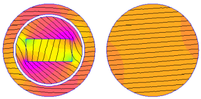
Figure 3: Finite element solution for a rotor angle of 45 degrees.
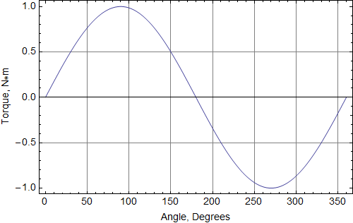
The Mathematica notebook TorqueBenchmark.nb evaluates the torque at 1 degree increments through a complete rotation. The torque computed for select values of angle is shown in Table 1, and the torque over the entire rotation is plotted in Figure 4. Agreement to the analytically predicted torque is good.
| Rotor Angle | FEMM Torque, Nm | Exact Torque, Nm |
| 0o | 7.75129*^-7 | 0. |
| 10o | 0.173658 | 0.173648 |
| 20o | 0.342031 | 0.342020 |
| 30o | 0.500019 | 0.5 |
| 40o | 0.642813 | 0.642788 |
| 50o | 0.76607 | 0.766044 |
| 60o | 0.866058 | 0.866025 |
| 70o | 0.93973 | 0.939693 |
| 80o | 0.984849 | 0.984808 |
| 90o | 1.00004 | 1. |

Figure 4: Simulation torque results.
3 Conclusions
A problem with rotation model via FEMM's air gap boundary condition has been compared in a problem where an analytical solution is available. In this problem the torque error is small (<0.01%) and the torque varies smoothly throughout a complete rotation.
| File | Last modified | Size |
|---|---|---|
| TorqueBenchmark.fem | 2018-02-26 04:57 | 3Kb |
| TorqueBenchmark.nb | 2018-02-26 05:13 | 38Kb |
| TorqueBenchmark.pdf | 2018-03-03 07:48 | 146Kb |